Testing and optimization
For simplicity, this guide will refer to both samples and applications as “applications”.
Each application in the nRF Connect SDK comes with its own testing instructions. Follow these instructions to make sure that the application runs as expected.
Information about the current state of the application is usually provided through LEDs, Universal Asynchronous Receiver/Transmitter (UART), or both. See the user interface section of the application’s documentation for the LED states or available UART commands.
To see the UART output, connect to the development kit (DK) with a terminal emulator. The default serial port settings are the following:
Baud rate |
Data bits |
Stop bits |
Parity |
|
|---|---|---|---|---|
115200 |
8 |
1 |
No parity |
None |
Use one of the following methods:
You can use the nRF Connect Serial Terminal app, which you can install from nRF Connect for Desktop. It establishes serial communication with the device, sends commands through UART, and also displays the UART output.
The app is available for Windows, Linux, and macOS.
To connect to the DK with Serial Terminal, complete the following steps:
Open the Serial Terminal app.
Connect the DK to the PC with a USB cable.
Power on the DK.
Click Select Device and select the particular kit entry from the drop-down list in the Serial Terminal.
Select the serial port you want to connect to from the drop-down list.
Configure the serial port connection parameters using the default serial port connection settings listed at the top of this page.
Click Connect to port.
nRF Connect Serial Terminal starts the serial communication with the kit.
For more information about how to connect using the app, see the steps in the Serial Terminal documentation.
The nRF Connect for VS Code extension includes an integrated serial port and RTT terminal, which you can use to connect to your board. For detailed instructions, see How to connect to the terminal on the nRF Connect for Visual Studio Code documentation site.
The extension is available for Windows, Linux, and macOS.
PuTTY is an open-source terminal emulator, available only for Windows.
To connect to the DK with PuTTY using CDC-UART, complete the following steps:
Open the PuTTY application.
Connect the DK to the PC with a USB cable.
Power on the DK.
Select Serial as the Connection type under Basic options for your PuTTY session.
The text fields above the selection change to Serial line and Speed.
Click the Terminal category in the category selection tree to see options controlling the terminal.
Enable the following options:
Implicit CR in every LF
Implicit LF in every CR
Local echo: Force on
Local line editing: Force on
PuTTY configuration for sending commands through UART
Click the Serial category under the Connection category in the category selection tree to see options controlling the local serial line.
Type the COM port corresponding to your DK in the Serial line to connect to field.
Depending on what devices you have connected to your computer, you might have several choices. To find the correct port:
Right-click on the Windows Start menu, and select Device Manager.
In the Device Manager window, scroll down and expand Ports (COM & LPT).
Find the port named JLink CDC UART Port and note down the number in parentheses.
If you have more than one J-Link UART Port, unplug the one that you want to use, plug it back in, and observe which one appeared last.
Your DK can show up as two consecutive COM ports. If this is the case, you need to test which COM port is the correct one.
Configure the settings in the Configure the serial line section using the default serial port connection settings listed at the top of this page.
Click Open.
The terminal window opens.
Note
You can connect using RTT also from the nRF Connect for VS Code extension. For detailed instructions, see How to connect to the terminal on the nRF Connect for Visual Studio Code documentation site.
SEGGER’s J-Link RTT Viewer is available for Windows, Linux, and macOS. You can install it as part of the J-Link Software and Documentation Pack.
To view the logging output using Real-Time Transfer (RTT), modify the configuration settings of the application to override the default UART console:
CONFIG_USE_SEGGER_RTT=y
CONFIG_RTT_CONSOLE=y
CONFIG_UART_CONSOLE=n
To run RTT on your platform, complete the following steps:
From the J-Link installation directory, open the J-Link RTT Viewer application:
On Windows, the executable is called
JLinkRTTViewer.exe.On Linux, the executable is called
JLinkRTTViewerExe.On macOs, the executable is called
JLinkRTTViewer.app.
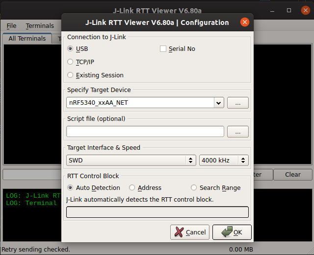
Select the following options to configure your connection:
Connection to J-Link: USB
Target Device: Select your IC from the list
Target Interface and Speed: SWD, 4000 KHz
RTT Control Block: Auto Detection

Click OK to view the logging output from the device.
The nRF Connect SDK provides a common set of features and options for debugging and optimizing the application performance. This includes a multilevel logging system that can be enabled and configured independently for different modules and logging backends (such as UART, J-Link RTT or Spinel), and support for writing unit tests using Unity and CMock.
Note
If you want to go through dedicated training related to some of the topics covered here, enroll in the nRF Connect SDK Intermediate course in the Nordic Developer Academy.
